
Microcontroller Design
For successful and elegant controller circuitry.
Microcontroller Basics
Controller such as ATMEGA32U4 are often used as low-cost, low-power processing units for mechanical keyboard PCBs.
They often require various components of their own in order to function properly.
Choosing the Correct Controller
Space and function constraints will require different choices of controllers.
| ATMEGA Series | Pros | Cons |
|---|---|---|
| atmega32u2 |
|
|
| atmega32u4 |
|
|
| at90usb1286 |
|
|
| atxmega32a4u |
|
|
When in doubt, pick 32u2 for sub-60%, 32u4 for 60-80% and splits, and 1286 for 80+% keyboards.
When using 32u2, it is strongly recommended to bind B7 to PWM backlight, since it is the only pin known to work with QMK flawlessly.
Controller Layout - The Basics
- Place the controller and its components in a position that allows for proper placement and breakout.
- All decoupling capacitors must be placed as close to VCC/GND pin pairs on the controllers as possible. (Detailed below)
- Break out other pins with even spacing and pattern in order to minimize wasted space.
- Try to keep "dirty ground current", such as from RGB LEDs or backlighting, away from the controller. For example, run a separate ground plane for the controller, and join it together with the rest of the ground close to the USB port.
Crystal Layout
General
- The crystal is one of the most sensitive parts of the controller circuit.
- Place the crystal in a well-shielded position away from other traces.
- Do not run any traces close to, through, or under the crystal area unless absolutely necessary.
- Crystal and its decoupling capacitors should be fairly close to the controller.
- Crystal layout should be relatively symmetrical.
- "Dirty ground current" should never run through the crystal.
- Do not use vias in crystal traces, since they mess with the fine capacitance requirements.
- Surround the zone with a ground plane.
Crystal Load Capacitors
- Recommended load capacitor range is from 10pf to 33pf.
- Atmel uses 22pf on their official documentation.
- For calculating exact capacitance for a crystal, use the following equation:
Capacitance for each crystal = 2 * (Crystal Load Capacitance) - 2 * (Stray Capacitance) - Crystal Load Capacitance can be found from the crystal datasheets.
- Stray capacitance comes from the traces of the board itself.
- Usually it is around 2-5pf provided that the crystal traces are short, matched, and have no vias.
Controller Decoupling Capacitors
Placement is important
- The microcontroller decoupling capacitors exist to prevent the controller from unleashing plenty of noise into the VCC and GND channels.
- Yes, a whole board can fail if these lines are affected enough.
- Place each decoupling capacitor as close to its respective VCC/GND pin pair as possible.
- Feed through the capacitor for them to have effect.
Choosing the right values
- Consult the official documentation and working prototypes for "correct" quantity and values.
- Official documentation will usually state 0.1uF per VCC pin and 10uF for UVCC pin.
- However, most common implementations will skip a 0.1uF to cut costs, and still run perfectly fine (i.e. Teensy 2.0, Teensy++ 2.0).
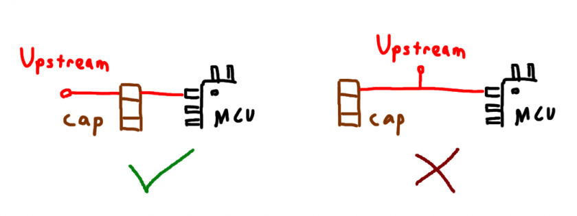
Regarding placement of the large capacitor
- Placing the largest decoupling capacitor far from the microcontroller makes it a power reservoir for the entire board.
- Placing the largest decoupling capacitor close to the microcontroller makes it a power reservoir for mainly the controller.
- Most sources will say that the largest decoupling capacitor should be placed close to the controller instead of near the USB port.
- It can be used as an "upstream filtering capacitor" by having all VCC current for the MCU travel across the capacitor pad before branching off to feed other VCC pins through their decoupling capacitors.
Sources
http://www.atmel.com/Images/Atmel-2521-AVR-Hardware-Design-Considerations_ApplicationNote_AVR042.pdf
https://blog.adafruit.com/2012/01/24/choosing-the-right-crystal-and-caps-for-your-design/
https://electronics.stackexchange.com/questions/20255/how-far-is-too-far-when-routing-traces-for-crystals-and-how-asymmetrical-is
http://www.atmel.com/Images/Atmel-8128-Best-Practices-for-the-PCB-Layout-of-Oscillators_ApplicationNote_AVR186.pdf
https://www.pjrc.com/teensy/schematic.html
https://www.silabs.com/documents/public/application-notes/AN0046.pdf