
PCB Guide Part 3 - Creating the MCU schematic
By this point, you should have installed the programs, created the repository, and added the local libraries.
Step 5. Beginning the schematic
The schematic is used to set up the electronics side of things.
For this tutorial, we will be using the typical Atmega32u4 microcontroller, and building a 2x2 macropad with MX and Alps support.
Open up the schematic editor to begin.
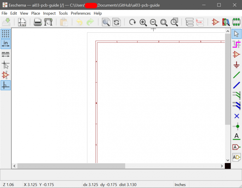
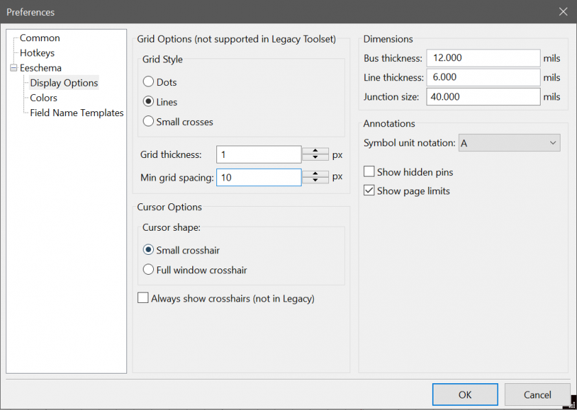
One modification used during this guide is seting the grid size to half the default size.
This allows a bit finer grain control for wiring things.
From Preferences -> Preferences -> Display options, set the grid size to 10.
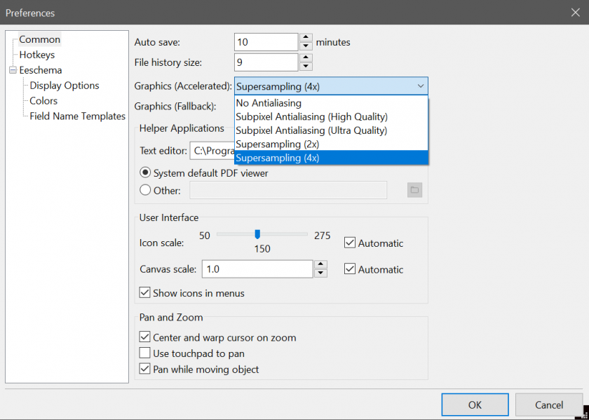
Also, if you want the super HD 8K experience while making your schematic, you can swap the graphics settings in the Common page.
From Ruiqi Mao's PCB guide, here is a nice commands reference:
m: pick the component up and move it
g: drag the component up and move it while keeping wires attached to it
c: copy the component
e: edit the component
r: rotate the component
y: mirror the component
del: delete the component
esc: abort!
Also, these shortcuts are useful to know:
w - Begin drawing a wire connection
k - Cut a wire and stop drawing it without clicking on an endpoint
Ctrl + h - Place a global net
The microcontroller, or MCU for short, is the brain of the PCB.
It cannot function on its own, so we will build the circuit for it.
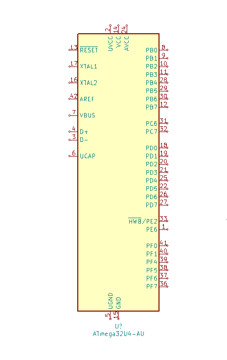
First, press A to open the "add symbol" menu, and search for atmega32u4.
Select the atmega32u4-au component.
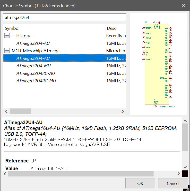
Place it down in the schematic.
To set it up, we will simply follow two resources:
- The technical data provided by the official datasheet.
http://ww1.microchip.com/downloads/en/devicedoc/atmel-7766-8-bit-avr-atmega16u4-32u4_datasheet.pdf - An existing "tried and tested" schematic used on the PJRC Teensy.
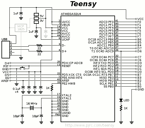
Usually, both a technical datasheet and an existing implementation will exist for most components.
Search for both, and use both as reference.
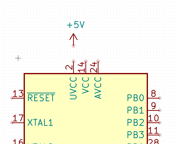
To begin, let's tie UVCC, VCC, and AVCC to +5V, as specified by the datasheet.
Hit P to open the power symbols menu, and select the +5V symbol.
Place it above the VCC pins. If you misplace, you can move it by hovering over the component and pressing M.
Now, wire it together using the wire tool (hotkey W).
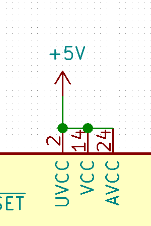
This binds the physical UVCC/VCC/AVCC pins on the component to the +5V net.
Net refers to a set of pads that should all be connected together.
Similarly, bind the GND and UGND pins to Ground by selecting the GND symbol in the power menu and wiring them together.
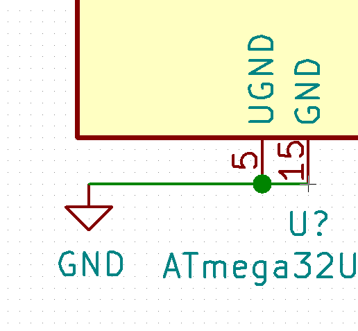
Protip: It is good practice to have positive power source symbols pointing up, and ground power symbols pointing down.
Now we will place some components.
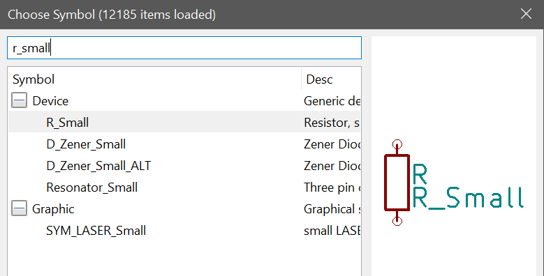
The HWB pin requires a pull-down resistor, or a resistor connected to ground.
Open the components menu with A, and search for r_small, or the small resistor component (The large one is massive and will burn space on the schematic):
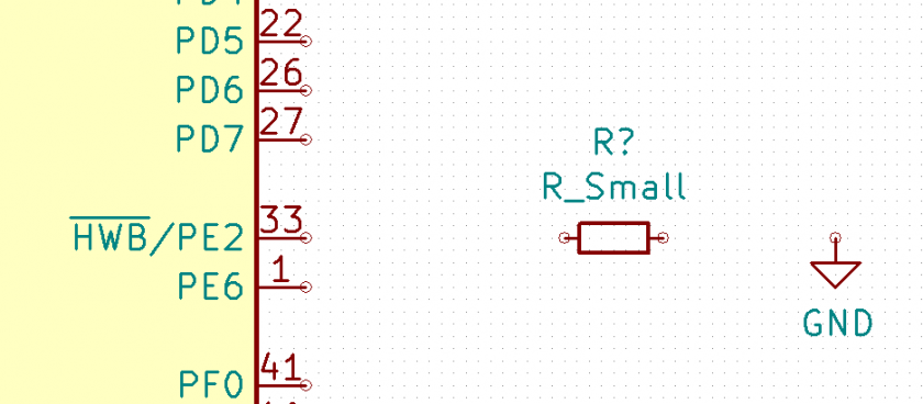
Now, place this parallel to the pin labeled HWB/PE2. You can rotate the component by pressing R.
Also, place a ground symbol.
Now, wire it together.
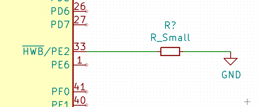
Congratulations, now the PE2 pin is connected to ground through the resistor.
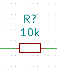
Let's change the value of the resistor. Press the E key while hovering over the resistor to edit.
A 10k ohm resistor is fit for this task. Select the value field, and type 10k.
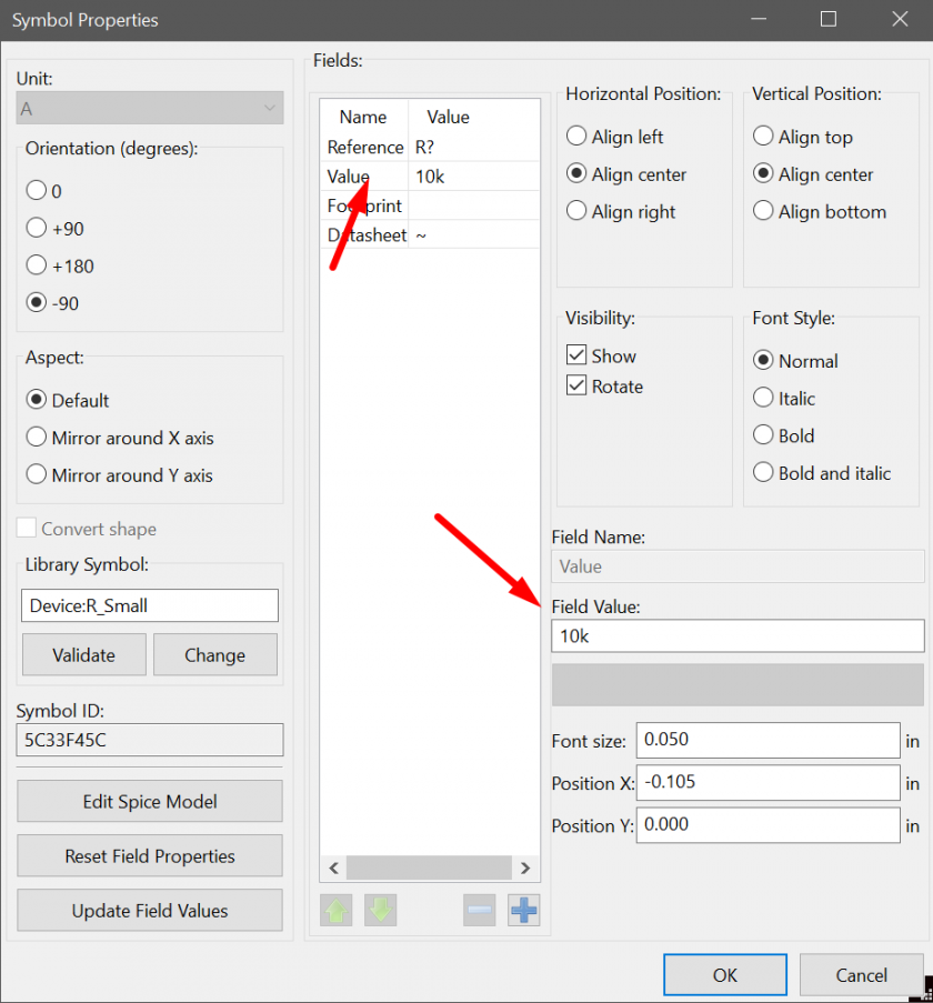
The component's value should now be updated.
The USB pins also need resistors. Repeat the previously described commands to place two 22 ohm resistors, and wire them.
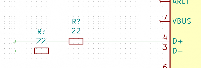
In this case, I drew the wire out on the other side as well, and used the K hotkey to end the wire at those points.
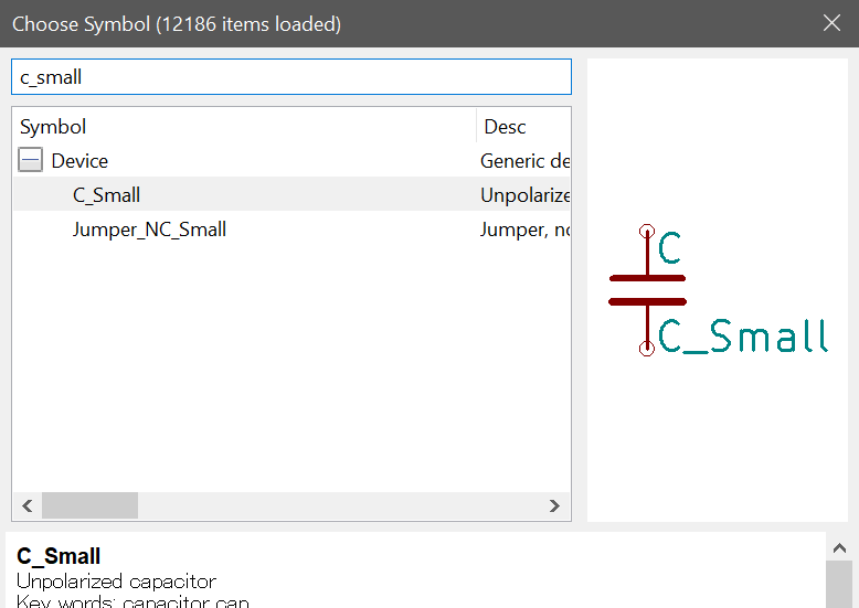
Now, let's place needed capacitors.
Through the add components menu, search for c_small (Again, regular capacitor symbol is massive).
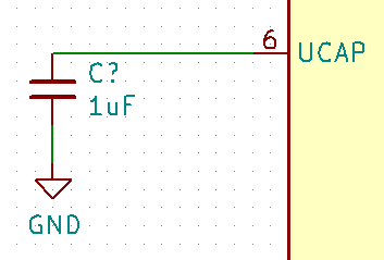
First, place a capacitor with value 1uF beside the UCAP pin, and connect the other end to ground.
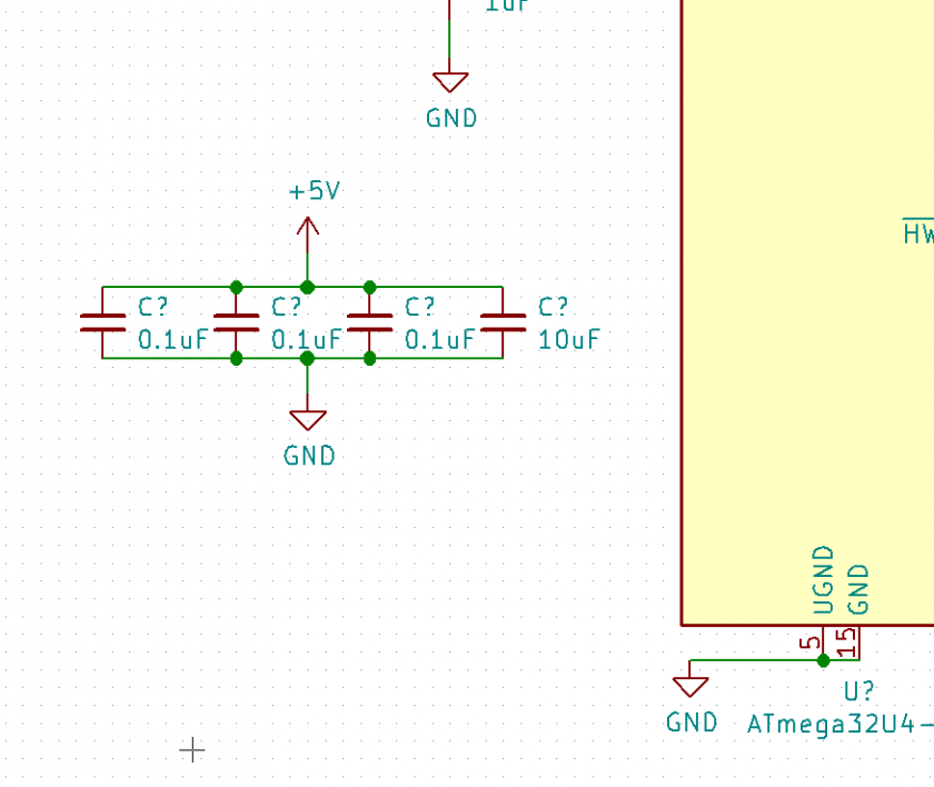
Next, we want to set up our decoupling capacitors. These are important capacitors that filter out electrical noise coming from the microcontroller.
The official documentation states to have a 0.1uF by each VCC pin (Which would be 4 on a 32u4), and a 10uF overall.
However, the Teensy schematic uses only three 0.1uF, and a 1uF overall.
I personally combine them - three 0.1uF and one 10uF. This has been confirmed functional by my testing.
Place them in an empty space close to the microcontroller, and bind one end to +5V, one end to Gnd.
Protip: Build one 0.1uF capacitor, and clone it using C to save time.
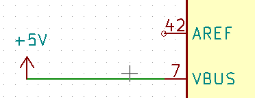
Since this PCB will get its power from USB no matter, bind VBUS to +5V.
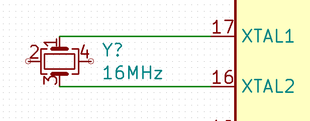
The crystal controls how fast the controller functions.
Search for the Crystal_GND24_Small component...
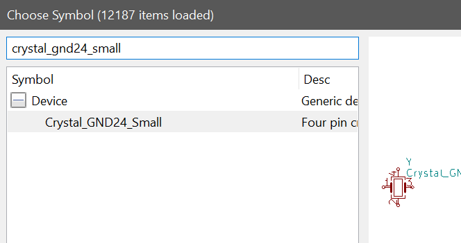
...and wire the non-gnd pins (1 and 3) to XTAL1 and XTAL2.
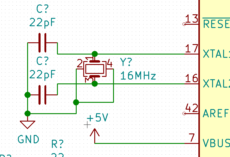
The crystal also needs load capacitors of its own.
Place two 22pF capacitors between each crystal pin and Gnd.
Also, wire the Gnd pins on the crystal to Gnd.
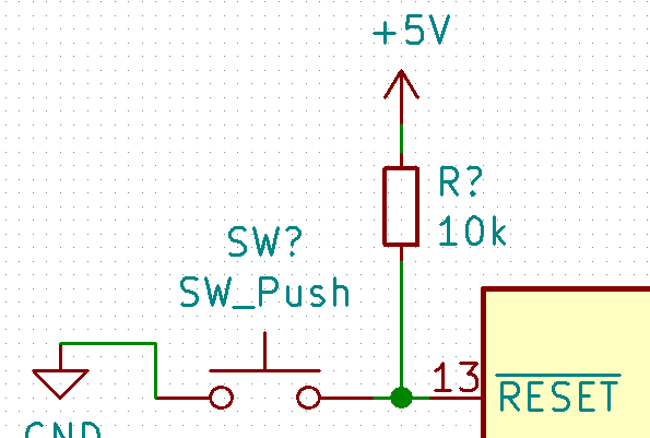
Also, an external pull-up resistor can prevent the reset pin from being read faultily, and accidentally resetting during use.
For this, a 10k ohm resistor can be placed between reset and +5V.
The AREF pin is ignored since we won't be doing analog readings.
Now let's place global nets on the USB lines - These connect wires together by name, removing the need for ugly wires that cut across the entire schematic.
Hit Ctrl+H, type the names, and place them on the other end of the USB positions.

Local nets also work, but I prefer global nets since they are much more visible.
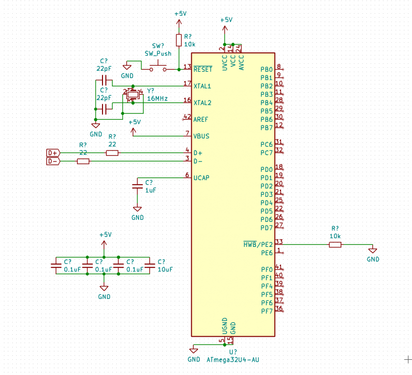
A view of the completed MCU zone.
Now, it's time to complete the rest.